The goal for this litle project was to learn the two-wire interface, which it makes possible to connect devices (up to 119)
only with four lines: ground, power, clock and data.
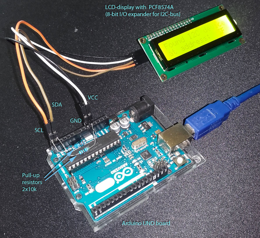
Please take a look on this piece of code, which demonstrates the use of the LCD display connected
to the arduino uno board through the PCF8574 interface.
I used a standard library for the two-wire interface (Wire.h) and the LCD library (LiquidCrystal_I2C.h)
by John Rickmann (originally by Marco Schwartz) from here.
The theory and praxis to the I2C is taken from the publication Interfejs I2C of Cezary Klimasz
available here.
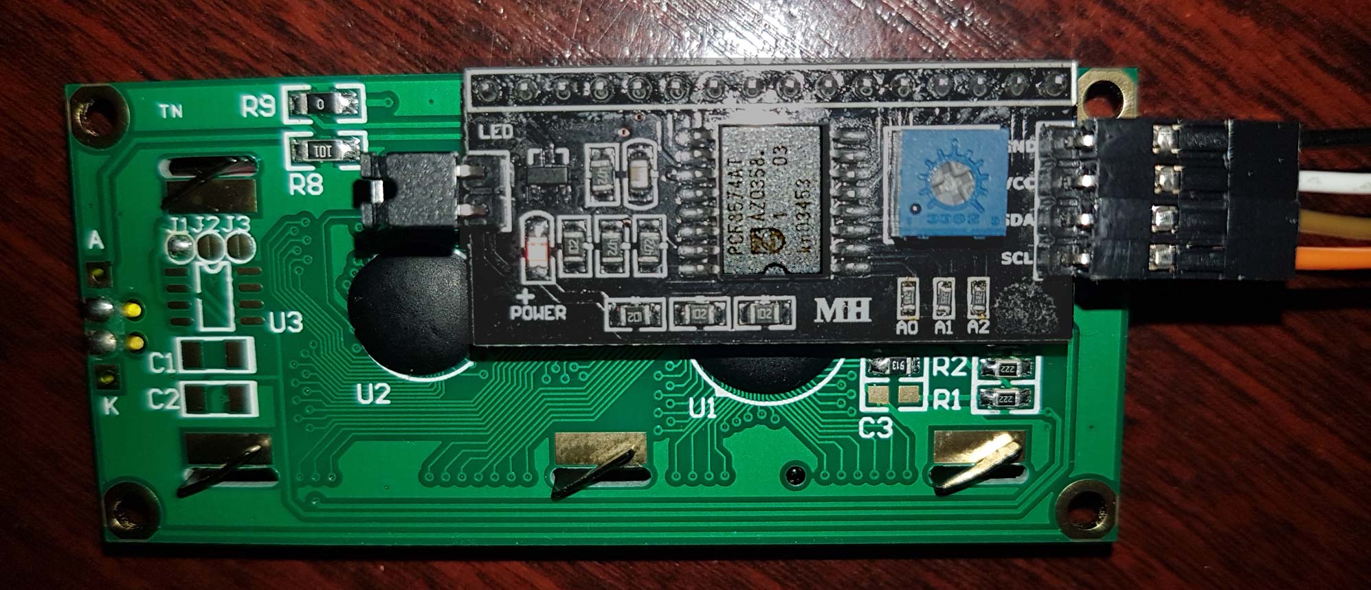
The internal address of the interface is 0x3F, which is calculated from the pin connectivity of A2-A0 lines on the PCF8574A.
In this case all 3 lines are on high state (111) and together with the constant A6-A3 (0111) results in 0x3F for the 7-bit
hex-address without R/W.
On power-on or when the reset button has been pressed the initialization of the LCD display occures.
LiquidCrystal_I2C lcd(0x3F, 16, 2);
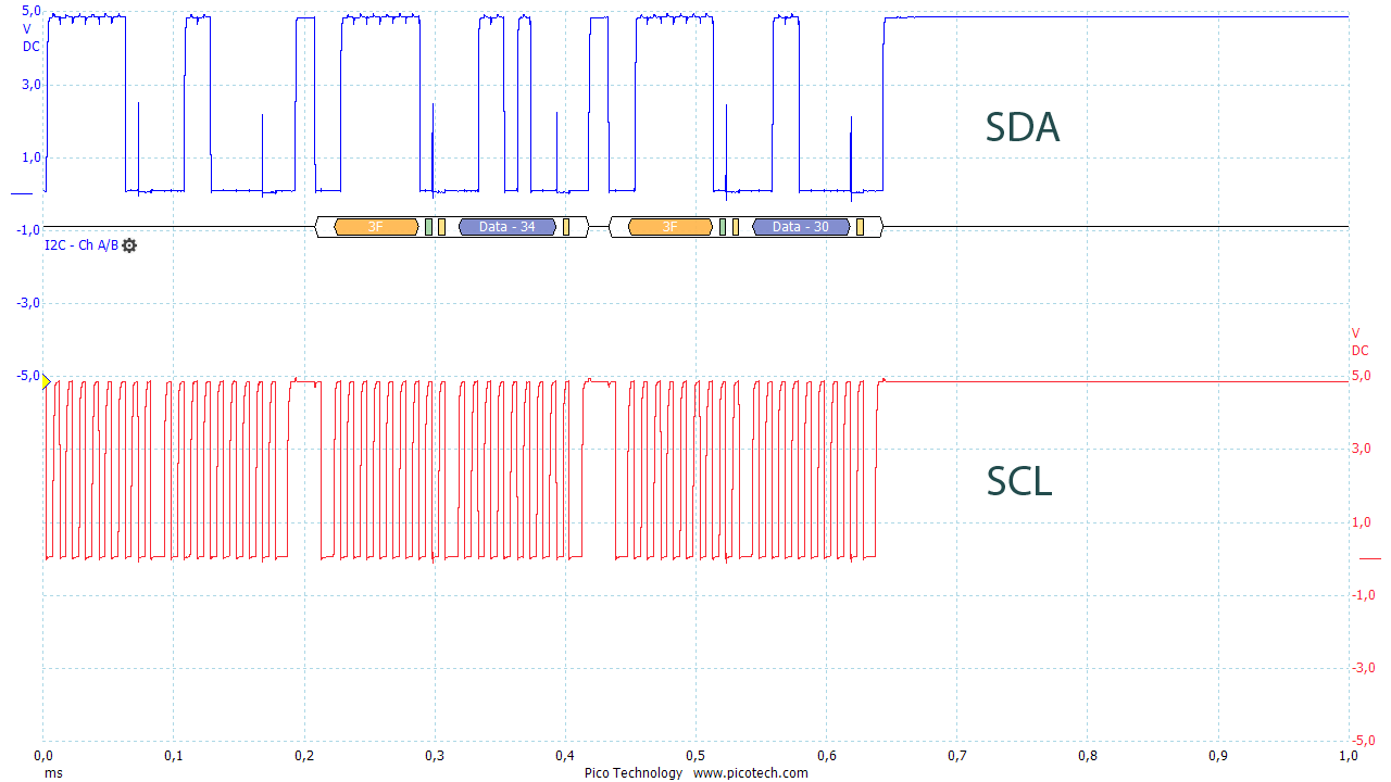
On this osciloscope diagram one can see two digits (4 and 0 as ASCII code) transmitted to the display controller,
each with a device address in front (0x3F).
This project is nothing special but it demonstrates the use of hardware in the high level environment.
The Unity software which is used for this simple project is used in the gaming industry.
This project uses in addition an Arduino board to control the game. The player drives a small tuk-tuk car on the street.
To control of the car four buttons are used connected to the input lines of AVR microcontroller, which in turn sends
the ASCII codes through the serial line to the Unity software. The software reacts on pressed buttons turning
the car to the left or to the right, accelerates or brakes the car.
Please see the code for connection to the Arduino board from the Unity software.
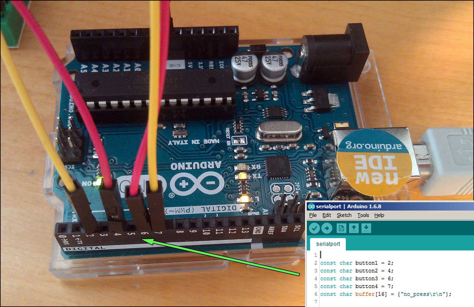
The Arduino is based on the Atmel 8-bit microcontroller ATmega328P.
The switches are not pulled up to the voltage by 1kOhm resistors. The input state can still be stable
because the pull up resistors are attached internally to the input lines inside of the microcontroller.
By pressing on the switch, the corresponding input line is grounded and its state changes.
The microcontroller can read this and reacts respectively.
Further, a different value for each switch is transmitted through the serial port.
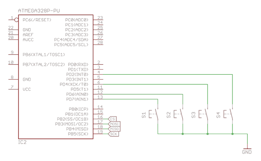
Please check out this very simple schematic.
The implementation for it is even more simple.
To forward the information a serial port on RS232 interface has been used, which can be max. 15m long.
The Ethernut
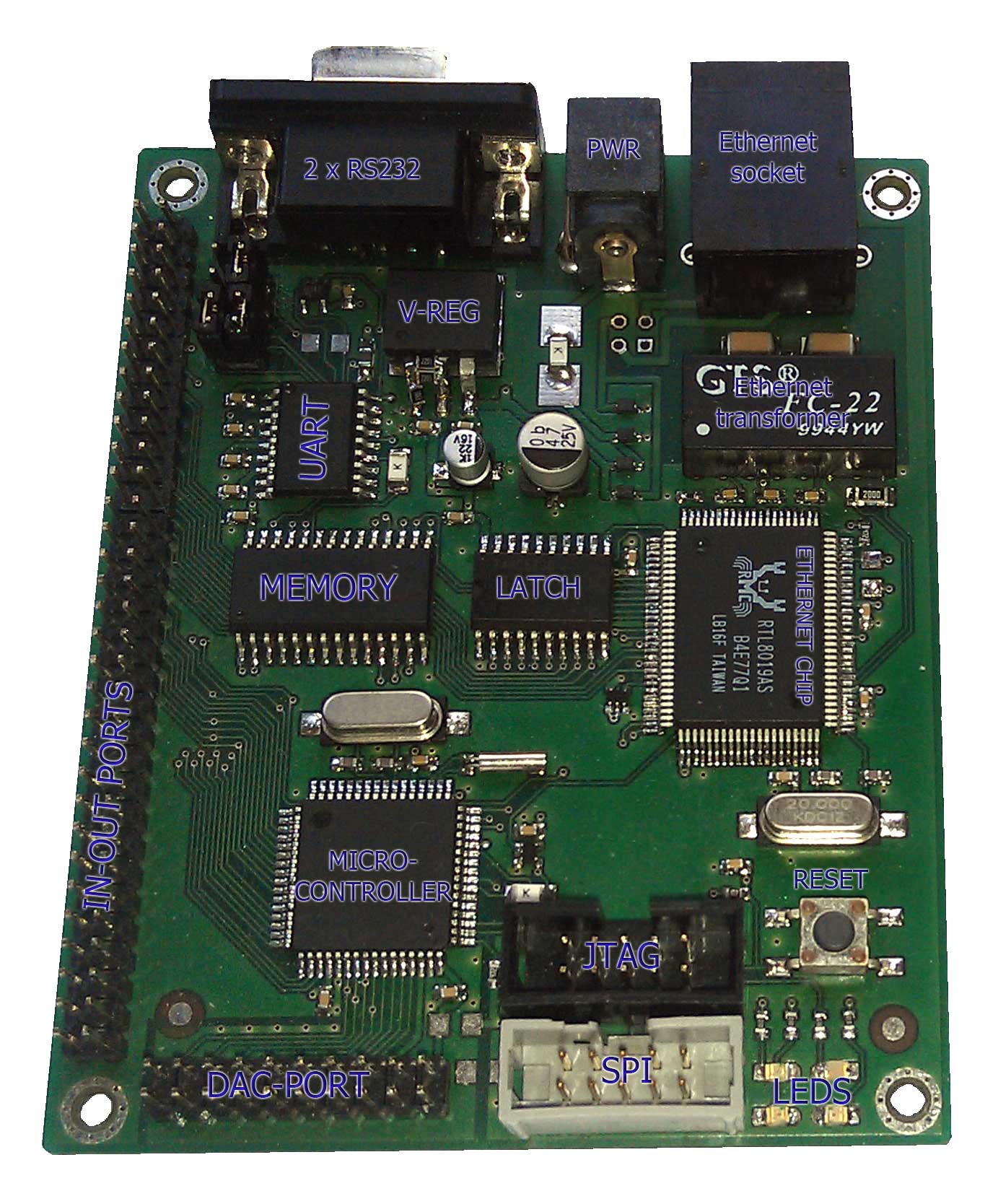
At my previous workplace I needed to grab the status of a machine and display it on a screen, so
the staff will see it and reacts if needed. To realize the idea I invented
a system contains of 3 parts
– embedded device, database, windows application, which is including hardware and software solutions.
The core point of the system is the embedded device, which is connecting to
the machine with protocols (eg. USS, Modbus or
H-protocol)
and sending the data through the serial connection to the database.
How it works?
- The embedded board sends a query message to the PLC or inverter.
- The machine controller (PLC or inverter) responds to the embedded board the message with data.
- The embedded board sends through RS232-connection the data to the database service application.
- The database service application adds data to the database server including the data-stamp.
- User interface gets the data and displays it.
For communicating with the hardware device on software level a protocol is needed.
Only USS-protocol has been implemented.
However there is possible to implement different protocols.
A LCD-display was used for displaying informations and debugging purposes.
The debug info cannot be send on the serial port, as both are obtained: one connects the PLC
and another the PC-application. However, the app could have a debug mode to display the values
from the embedded board. But it doesn't.
To connect the ethernut to the machine controller was necessary to build a RS232-RS485
converter. The schematic for the converter is accesible
here.
The MM75 (Siemens) operates with RS485 standard, while the embedded board operates with RS232.
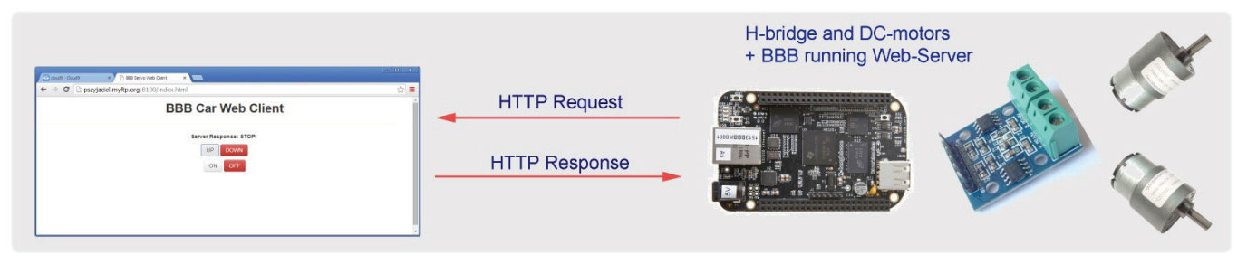
The BeagleBone Black 1.4
This project demonstrates the use of the Beaglebone. For this purpose a small car‐model was builded,
and remotely controlled using the WiFi network by the Beaglebone's microcontroller.
The project includes hardware and software solutions.
The car as mechanical part contains two DC-motors and a 14.4V battery.
The hardware controll unit is a PCB with H‐bridge circuit (HG7881),
the voltage regulators (7805, 7812 and LM1086) and the current drivers (ULN2003A).
The software includes a web‐server (PWM), which can communicate with a web browser from another PC via WebSocket protocol.
How it works?
When the user clicks on the buttons, the webpage
will fire an event, which sends the function name as text string to the
web‐socket‐controller.js. The websocket‐
controller.js receives the event and formats the command, which further will be send on port 8150
to the web‐socket‐server.js.
The web socket‐server handles the connection and it calls a proper function in
the bbb-pwm.js.
The bbb‐pwm.js writes the parameters to corresponding files of the device.
The see the video demonstrating the car driving on the floor please follow the link:
video